Stuck? How to Rotate Any LTspice Component in Just 3 Clicks
Are you an Electronics Student or Electronics Hobbyist who often feels stuck when trying to perfectly position Electronic Components in LTspice? You’re not alone! While LTspice, developed by Analog Devices, is an incredibly powerful Circuit Simulation and Schematic Capture tool, precisely arranging your Components can be a source of major frustration. Yet, proper Component orientation isn’t just about aesthetics; it’s critical for clear schematics and achieving accurate SPICE simulation results.
Good news! This guide will empower you to master the essential Rotate Component and Mirror Component functions in LTspice, making component placement intuitive and efficient. We’ll show you how to use powerful Keyboard Shortcuts and accessible Menu Options that will make you proficient in just a few key presses or ‘clicks’. Never be stuck again with LTspice Component Placement!
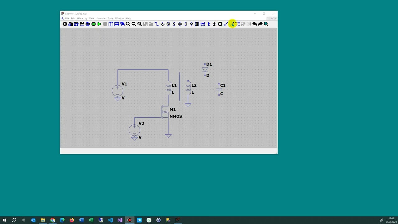
Image taken from the YouTube channel CodeDocu Developer C# Asp Net Angular , from the video titled LTSpice Rotate Device Element .
As we embark on our journey into circuit design, one of the very first challenges many aspiring electronics enthusiasts face is simply arranging their components on a schematic.
Stuck No More: Effortless Component Placement in LTspice Begins Here
Embarking on any electronics project, whether for study or hobby, often begins with a schematic. For many, LTspice quickly becomes an indispensable ally. Developed by Analog Devices, LTspice stands out as a powerful and widely-used Circuit Simulation and Schematic Capture tool. Its robust capabilities allow users to design, test, and analyze complex circuits before ever touching a soldering iron, making it a cornerstone for modern electronics development.
However, even with such a powerful tool at hand, a common frustration frequently surfaces for both Electronics Students and Electronics Hobbyists: the precise placement of Electronic Components. Dragging and dropping components onto the canvas can feel like an exercise in futility when they refuse to snap into place or align correctly. This can lead to cluttered, hard-to-read schematics that are a nightmare to debug.
Why Component Orientation Matters
The importance of proper Component orientation cannot be overstated. It’s not just about aesthetics; it critically impacts both the clarity of your schematics and the accuracy of your SPICE simulation results:
- Clear Schematics: A well-organized schematic is intuitive and easy to understand, not just for you but for anyone else who might need to review or work with your design. Proper alignment, rotation, and mirroring of components contribute significantly to this readability, making complex circuits comprehensible at a glance.
- Accurate Simulation Results: Many electronic components, such as diodes, transistors, and integrated circuits, are polarity-sensitive or have specific pin configurations. Incorrect orientation can lead to improper connections in the simulation, resulting in erroneous SPICE analysis or even non-functional circuits. Ensuring components are placed correctly from the outset prevents countless hours of troubleshooting.
This guide is designed to empower you to overcome these placement hurdles. We will delve into the core topic of mastering easy Rotate Component and Mirror Component functions in LTspice. You’ll discover how to leverage efficient Keyboard Shortcuts and accessible Menu Options to precisely position every resistor, capacitor, and IC. Our aim is to make you proficient in just a few key presses or ‘clicks’, transforming your component placement from a source of frustration into a streamlined, intuitive process.
Ready to get hands-on? Let’s start with the most fundamental manipulation: rotating components.
Having established that navigating LTspice component placement doesn’t have to be a source of frustration, let’s jump straight into the first, and arguably most crucial, method for arranging your circuit elements with precision.
The Essential Spin: How Ctrl+R Transforms Your LTspice Component Placement
When you’re designing a circuit in LTspice, the orientation of your components is vital not just for aesthetic appeal, but for clear readability and effective circuit simulation. Awkwardly angled resistors or misaligned capacitors can make your schematic confusing to interpret. Fortunately, LTspice provides a remarkably simple yet powerful keyboard shortcut to get your components perfectly aligned: Ctrl+R. This command is your go-to for rotating components, enabling you to quickly adjust their position by 90-degree increments, ensuring a clean and professional layout every time.
Understanding Ctrl+R: The Primary Rotation Shortcut
The Ctrl+R keyboard shortcut is the most fundamental and frequently used tool for component rotation in LTspice. It allows you to "spin" a selected or ghosted component clockwise in 90-degree steps. Whether you need a resistor to be horizontal instead of vertical, or a transistor to face a specific direction, Ctrl+R makes the adjustment instantaneous. It’s intuitive, quick, and becomes second nature once you start using it.
Step-by-Step Guide to Using Ctrl+R
Mastering Ctrl+R is straightforward. Follow these simple steps to rotate any component in your LTspice schematic:
- Open Your LTspice Schematic Capture Window: Begin by opening a new or existing
.ascfile in LTspice. - Select or Place an Electronic Component:
- For an existing component: Click directly on the component you wish to rotate. Once selected, its outline will typically change color or highlight.
- For a new component: Choose a component from the toolbar (e.g., the resistor icon, capacitor, NPN transistor, etc.) or press
F2to open the component library.
- Ensure the Component is Highlighted or ‘Ghosted’:
- If you’re rotating an existing component, it should be selected.
- If you’re placing a new component, it will appear as a ‘ghost’ outline attached to your cursor, ready for placement.
- Press Ctrl+R Repeatedly: With the component selected or ghosted, simply press Ctrl+R. Each press will rotate the component 90 degrees clockwise. Keep pressing until the component is in your desired orientation.
- Click to Finalize Placement: Once the component is oriented correctly, click your left mouse button to place it on the schematic. If it’s an existing component, releasing the mouse button (if you were dragging it) or deselecting it will confirm the rotation.
Practical Examples and Utility
The utility of Ctrl+R becomes immediately apparent when you’re laying out even the simplest circuits. For instance:
- Orienting a Resistor: By default, resistors are often placed horizontally. If you need a resistor to stand vertically to connect between two horizontally aligned wires, simply select the resistor (or call it up for placement) and press Ctrl+R once. It will instantly rotate 90 degrees, ready for vertical connection.
- Capacitor Orientation: Capacitors might need to be horizontal or vertical depending on the circuit flow. Ctrl+R allows you to cycle through these orientations effortlessly.
- Transistors and Diodes: For directional components like transistors, diodes, or op-amps, Ctrl+R is essential for ensuring their pins align with the intended connections, which is crucial for accurate Circuit Simulation. Correct orientation can significantly improve the clarity and readability of complex schematics.
This method is by far the fastest and most common way to rotate components in LTspice, saving you valuable design time and leading to more organized and professional-looking schematics.
How Ctrl+R Affects Common Components
The effect of Ctrl+R is uniform across most components, rotating them clockwise by 90 degrees with each press. The table below illustrates how common components typically rotate:
| Component Type | Initial Orientation | After 1x Ctrl+R (90° Clockwise) | After 2x Ctrl+R (180° Clockwise) | After 3x Ctrl+R (270° Clockwise) |
|---|---|---|---|---|
| Resistor | Horizontal | Vertical | Horizontal | Vertical |
| Capacitor | Vertical | Horizontal | Vertical | Horizontal |
| Inductor | Horizontal | Vertical | Horizontal | Vertical |
| Diode | Horizontal (Anode Left) | Vertical (Anode Up) | Horizontal (Anode Right) | Vertical (Anode Down) |
| NPN Transistor | Standard (Emitter Down) | Rotated 90° CW | Inverted (Emitter Up) | Rotated 270° CW |
While Ctrl+R is your primary tool for rotational adjustments, there are instances where merely spinning a component isn’t enough; sometimes, you need to mirror it for ultimate schematic clarity.
While spinning components with Ctrl+R is a fundamental skill, sometimes you need more than just a turn to get your circuit layout just right.
When Spin Isn’t Enough: Ctrl+E and the Art of Flipping Components for Flawless Schematics
Beyond simply rotating a component to change its angular position, LTspice offers another powerful tool for orienting elements on your schematic: mirroring. This crucial action allows you to flip a component across an axis, effectively reversing its internal connections or physical layout. The key to unlocking this capability lies with the intuitive keyboard shortcut: Ctrl+E.
Understanding the Flip: Mirror vs. Rotate
It’s vital to grasp the core difference between rotating and mirroring, as misunderstanding can lead to incorrect circuit simulations.
- Rotation (Ctrl+R): This action changes the angular position of a component. Think of it as spinning the component on its central axis. A resistor rotated 90 degrees still functions the same way, just oriented differently.
- Mirroring (Ctrl+E): This action flips the component across an invisible axis, effectively changing its handedness or the relative positions of its terminals. This is especially critical for polarized components like Diodes and many Transistors. For instance, mirroring a diode will switch its anode and cathode connections, fundamentally altering its direction in the circuit. Mirroring a transistor can flip its collector and emitter or source and drain connections, which is essential for correct circuit operation and readability.
Step-by-Step Guide: Mastering the Ctrl+E Mirror
Using Ctrl+E to mirror an electronic component in LTspice is straightforward and can be done during the initial placement phase.
- Select a Component: Begin by selecting the desired Electronic Component from your LTspice library. For this example, consider choosing a Diode (like
Dfor a standard diode) or a Transistor (e.g.,NPNfor an NPN BJT). - Initiate Placement: Click on your Schematic Capture workspace to bring the component onto the drawing area. At this point, the component will be attached to your cursor, ready for placement, but its position is not yet finalized.
- Perform the Mirror Action: While the component is still "floating" with your cursor, press the Ctrl+E keyboard shortcut.
- Observe the Flip: You will immediately notice how the component’s orientation flips across its axis. For a Diode, the triangle direction will reverse, effectively swapping the anode and cathode. For a Transistor, its pins (Base, Collector, Emitter for BJTs; Gate, Drain, Source for MOSFETs) will swap their relative positions horizontally or vertically, depending on the component’s internal design and the mirroring axis.
- Finalize Placement: Once the component is mirrored to your desired orientation, click your mouse button to place it permanently onto the schematic.
Why Mirroring Matters: Practical Applications in LTspice
Mirroring isn’t just a cosmetic change; it’s often essential for correct Circuit Simulation and for creating clear, readable schematics that adhere to conventional electrical engineering diagrams.
- Reversing a Diode’s Direction: Perhaps the most common use case. If you need a diode to conduct current in the opposite direction from its default placement, mirroring it with Ctrl+E is the quickest way to achieve this, correctly swapping its anode and cathode terminals.
- Flipping a Transistor: For Transistors, mirroring can be crucial when designing circuits where the input and output connections need to be on specific sides of the component. For instance, you might need the emitter of an NPN transistor on the left for a common-emitter configuration or the drain of a MOSFET on top for clarity in a switching application. Mirroring ensures the physical representation on your schematic matches the intended current flow and signal paths.
The table below illustrates how Ctrl+E specifically mirrors components like Diodes and Transistors, showing their states before and after the action.
| Component Type | Initial Placement (Before Ctrl+E) | Mirrored State (After Ctrl+E) | Practical Impact |
|---|---|---|---|
| Diode |
Anode on left, Cathode on right (e.g., pointing right) |
Anode on right, Cathode on left (e.g., pointing left) |
Reverses current flow direction (swaps Anode/Cathode). Critical for power supply rectification, clamping, etc. |
| NPN Transistor |
Base on left, Collector top, Emitter bottom (common orientation) |
Base on right, Collector top, Emitter bottom (horizontal flip) |
Switches side for Base connection. Useful for neat wiring or matching circuit diagrams where inputs/outputs are on specific sides. |
| NMOS Transistor |
Gate on left, Drain top, Source bottom |
Gate on right, Drain top, Source bottom (horizontal flip) |
Switches side for Gate connection. Essential for clear signal paths in logic or switching circuits. |
By mastering Ctrl+E, you gain precise control over the orientation of polarized components, ensuring your LTspice schematics are not only visually clear but also accurately represent your intended circuit functionality.
Of course, keyboard shortcuts aren’t the only way to precisely position your components; sometimes, the classic menu options offer the control you need.
While Ctrl+E offers a quick flip, sometimes the most straightforward path to precise schematic design lies in the familiar click of a mouse.
The Menu’s Touch: Effortless Component Control Through LTspice’s Classic Options
Though keyboard shortcuts like Ctrl+R for rotation and Ctrl+E for mirroring are undoubtedly efficient and beloved by experienced users for their speed, LTspice also provides an equally robust and highly accessible alternative: the comprehensive Menu Options. These classic methods ensure that every user, regardless of their familiarity with keyboard commands, can precisely position their electronic components with ease and confidence. For those who prefer a more visual, mouse-driven interaction, or are just beginning their journey into LTspice, the menu-based approach offers a clear, step-by-step path to manipulating elements within your schematic.
Spinning Your Components: The Three-Click Rotate
Rotating a component using the Menu Options is a simple process that requires just a few clicks, making it an intuitive method for precise adjustments. This is particularly useful when you need to align pins or orient a device to improve readability.
Here’s how to rotate a component using the classic menu method:
- Place or Select: Begin by either placing a new electronic component onto your LTspice schematic canvas, or by clicking to select an existing component that you wish to rotate.
- Right-Click for Context: Move your mouse cursor directly over the chosen component and perform a right-click. This action will open a context-sensitive menu specific to the selected item.
- Choose ‘Rotate’: From the list of menu options that appear, simply select ‘Rotate’. With each selection, your component will spin 90 degrees clockwise, allowing you to achieve the perfect orientation.
Flipping Your Components: The Three-Click Mirror
Just like rotation, mirroring a component via the Menu Options is a straightforward three-click operation. This function is essential for creating clean, logical schematics, especially when dealing with symmetric parts or ensuring proper signal flow.
Follow these steps to mirror a component using the menu:
- Place or Select: First, either place a new electronic component onto your LTspice schematic, or select an existing one that you intend to mirror.
- Right-Click for Context: Position your mouse cursor directly on top of the chosen component and execute a right-click. This will reveal the context menu tailored to the selected component.
- Select ‘Mirror’: Within the context Menu Options, locate and select ‘Mirror’. Your component will instantly flip horizontally, providing the mirrored orientation you need for your schematic.
When to Opt for the Menus
While keyboard shortcuts are fantastic for speed once mastered, there are several scenarios where utilizing the Menu Options for component positioning becomes the preferred choice. For new electronics students, the visual feedback and discoverability offered by right-clicking and seeing available actions can significantly aid in learning the LTspice interface. It allows them to explore functions without needing to memorize specific key combinations immediately. Furthermore, some users simply find mouse-based interaction more convenient or natural, especially during initial schematic layout or when making less frequent adjustments. The Menu Options provide a clear, step-by-step approach that removes any guesswork, ensuring accurate placement every time.
By understanding both keyboard shortcuts and the classic menu approaches, you’re well on your way to mastering LTspice and creating professional-grade schematics.
While we’ve thoroughly explored the classic menu-driven approach for precise component placement, the true hallmark of an efficient schematic designer often lies in mastering direct, intuitive manipulation techniques.
Unlock Schematic Superpowers: Mastering LTspice’s Essential Component Commands
Creating clean, readable, and functional schematics in LTspice goes far beyond simply dropping components onto the canvas. It’s about organizing them logically, routing connections efficiently, and presenting your circuit in a professional manner. At the heart of achieving this lies the simple yet incredibly powerful ability to rotate and mirror your electronic components, foundational skills that every electronics enthusiast should master.
The Core Commands: Rotate and Mirror for Efficiency
The beauty of LTspice lies in its streamlined workflow, especially when it comes to component manipulation. Gone are the days of tedious multi-step processes for basic adjustments. LTspice empowers you to instantly reorient and flip components with just a couple of key presses, dramatically speeding up your schematic capture process.
- Rotating Components (Ctrl+R): This fundamental command allows you to change the orientation of a selected component. Whether you need a resistor to be vertical instead of horizontal, or an op-amp pin to face a specific direction for cleaner wiring, Ctrl+R cycles through 90-degree rotations. It’s an invaluable tool for minimizing wire crossings and optimizing the visual flow of your circuit.
- Mirroring Components (Ctrl+E): Equally powerful is the mirroring function. This command effectively flips a selected component horizontally along its axis. For symmetrical components or situations where you need to reverse the order of pins (like for certain MOSFETs or ICs), Ctrl+E provides instant reversal, helping you align components perfectly without re-placing them.
While these keyboard shortcuts offer unparalleled speed, remember that these options are also accessible via the main menu, typically under "Edit" or by right-clicking a component, providing a flexible alternative for users who prefer a mouse-centric approach. However, the efficiency gained from internalizing Ctrl+R and Ctrl+E cannot be overstated.
Why Practice Matters: For Students and Hobbyists
For every electronics student and electronics hobbyist embarking on their journey through circuit design, consistent practice with these fundamental techniques is non-negotiable. It’s not just about knowing the shortcuts; it’s about making them second nature. Integrating Ctrl+R and Ctrl+E into your muscle memory will lead to:
- Faster Schematic Capture: Reduce the time spent on basic layout tasks, allowing you to focus more on the circuit’s functionality.
- More Organized Layouts: Easily align components, create neat rows and columns, and keep related parts grouped together, making your schematic easier to read and debug.
- Professional Schematics: A well-laid-out schematic isn’t just aesthetically pleasing; it’s a mark of a diligent designer. Professional schematics are less prone to errors and communicate design intent clearly.
The Link to Simulation Success and SPICE
Beyond mere aesthetics, mastering component manipulation has a direct impact on the effectiveness of your circuit simulation and your deeper understanding of SPICE. A poorly organized schematic, riddled with convoluted wiring and misaligned components, is a breeding ground for errors, both in design and in interpretation.
Clear component placement, achieved through proficient use of rotation and mirroring, ensures that:
- Connections are Evident: It’s easier to verify that all pins are connected correctly, reducing the chances of subtle wiring errors that can derail a simulation.
- Signal Flow is Clear: A logical layout helps you visually trace signal paths, which is crucial for understanding circuit behavior before, during, and after simulation.
- Debugging is Simplified: When a simulation doesn’t yield expected results, a tidy schematic makes it significantly easier to pinpoint potential issues, whether they are wiring mistakes or conceptual flaws.
Ultimately, these basic manipulation skills serve as a gateway to more effective circuit simulation and a deeper, more intuitive grasp of how your circuits behave under the hood, leveraging the power of SPICE models.
Embrace LTspice’s Power
LTspice stands out as an incredibly user-friendly yet profoundly powerful tool, and its intuitive component manipulation features are a testament to its design philosophy. Provided freely by Analog Devices, it offers an accessible entry point for learning sophisticated electronic design and circuit simulation. By embracing and mastering these fundamental features, you unlock its full potential, transforming the often-daunting task of schematic creation into an efficient and even enjoyable part of your electronic design process.
With these foundational component manipulation skills mastered, you’re now well-equipped to tackle more complex circuit designs and simulations with confidence.
Frequently Asked Questions About Stuck? How to Rotate Any LTspice Component in Just 3 Clicks
How do I quickly rotate a component in LTspice?
Simply select the component you wish to rotate and press Ctrl+R. This is the fastest way to rotate a component. Knowing how to girar o componente no lt spice4 is essential for efficient circuit design.
What if I accidentally rotate the component too many times?
Keep pressing Ctrl+R to continue rotating the component until it’s in the desired orientation. Remember, the command to girar o componente no lt spice4 is Ctrl+R.
Is there another way to rotate a component besides using the keyboard shortcut?
While Ctrl+R is the quickest, you can also right-click on the component and look for a rotate option in the context menu. However, the Ctrl+R method is preferred when you want to girar o componente no lt spice4.
What if the component doesn’t seem to be rotating?
Ensure the component is actually selected (highlighted). If it’s still not rotating after pressing Ctrl+R, try restarting LTspice. Sometimes, a simple restart can resolve unexpected behavior when you try to girar o componente no lt spice4.
You’ve now mastered the art of Component placement in LTspice! We’ve demystified how incredibly simple and efficient it is to manipulate your Electronic Components, whether you’re rotating them with the lightning-fast Ctrl+R or precisely mirroring them with Ctrl+E. Remember, these powerful Keyboard Shortcuts, complemented by the intuitive Menu Options, are your keys to professional-grade Schematic Capture.
To all Electronics Students and Electronics Hobbyists: embrace and practice these fundamental techniques. They are not just about neatness; mastering these basic Electronic Component manipulation skills is absolutely crucial for effective Circuit Simulation and forging a deeper understanding of SPICE. LTspice, a cornerstone tool from Analog Devices, is designed to be user-friendly and incredibly powerful. By applying these simple methods, you’re not just drawing circuits; you’re truly designing and analyzing them with confidence and precision. Go forth and create impeccably organized LTspice Schematics!
