PV Diagrams Demystified: Your Guide to Thermodynamics!
Understanding PV diagram thermodynamics is crucial for engineers working with systems modeled by Carnot cycles, and its graphical representation provides valuable insights into energy transfer. The First Law of Thermodynamics, a fundamental principle, underpins the interpretation of PV diagrams and their ability to illustrate work done and heat exchanged in thermodynamic processes. Institutions like the Massachusetts Institute of Technology (MIT) offer extensive resources on thermodynamics, enabling a deeper exploration of PV diagrams and their applications. Analyzing these diagrams often requires tools such as computer simulations, providing accurate representations of complex thermodynamic cycles. Our guide offers a comprehensive overview, making PV diagram thermodynamics accessible and understandable for anyone seeking a clearer grasp of this essential topic.
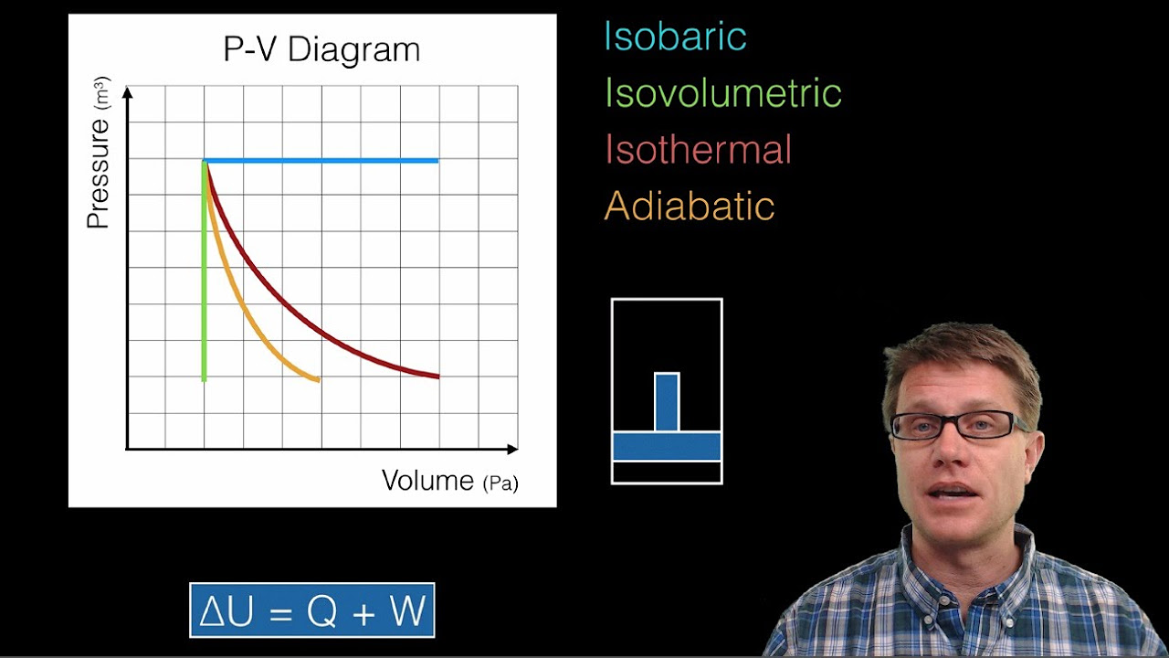
Image taken from the YouTube channel Bozeman Science , from the video titled Thermodynamics and P-V Diagrams .
PV Diagrams Demystified: Your Guide to Thermodynamics!
To effectively explain "pv diagram thermodynamics", the article layout should follow a logical progression, starting from fundamental concepts and building towards more complex applications. The goal is to provide a clear, accessible, and informative resource that demystifies PV diagrams for a broad audience.
Introduction to Thermodynamics and State Variables
The article should begin by establishing the context of thermodynamics. This section should offer a brief overview of thermodynamics, explaining its focus on energy and its transformations.
- Define thermodynamics in simple terms.
- Introduce key concepts:
- System
- Surroundings
- State of a system
Following the overview, introduce the essential state variables used to describe a thermodynamic system. These are pressure (P), volume (V), and temperature (T).
- Clearly define pressure (P), volume (V), and temperature (T).
- Explain the importance of these variables in describing the state of a system.
- Mention other relevant state variables (e.g., internal energy, enthalpy) if appropriate for later sections.
What is a PV Diagram?
This section provides the core definition of a PV diagram (pressure-volume diagram). This should be the heart of the "pv diagram thermodynamics" explanation.
- Define a PV diagram as a graphical representation of the relationship between pressure and volume of a system.
- Explain that the x-axis represents volume (V) and the y-axis represents pressure (P).
- Emphasize that each point on the diagram represents a specific state of the system.
- Describe how a path on the PV diagram represents a thermodynamic process.
Significance of Area Under the Curve
A critical aspect of PV diagrams is the area under the curve, which represents the work done by or on the system during a process. This subsection needs detailed explanation.
- Explain that the area under the curve represents the work (W) done during a process.
- Provide the mathematical formula for work: W = ∫PdV. Explain what the integral represents.
- Explain the sign convention:
- Expansion (increase in volume): Work done by the system (W > 0).
- Compression (decrease in volume): Work done on the system (W < 0).
- Include visual aids (diagrams) illustrating expansion and compression processes and the corresponding positive or negative work.
Common Thermodynamic Processes on PV Diagrams
This section will illustrate how different thermodynamic processes are depicted on a PV diagram.
- Introduce common thermodynamic processes:
- Isobaric Process: Constant pressure.
- Explain that this is represented by a horizontal line on the PV diagram.
- Give examples (e.g., heating water in an open container).
- Isochoric Process (Isovolumetric): Constant volume.
- Explain that this is represented by a vertical line on the PV diagram.
- Give examples (e.g., heating a gas in a rigid container).
- Isothermal Process: Constant temperature.
- Explain that this is represented by a hyperbolic curve on the PV diagram.
- Mention the ideal gas law (PV = nRT) and how it relates to the shape of the curve.
- Give examples (e.g., a slow compression of a gas with good heat exchange).
- Adiabatic Process: No heat exchange with the surroundings.
- Explain that this is represented by a curve steeper than an isothermal curve on the PV diagram.
- Mention the relationship PVγ = constant, where γ is the adiabatic index.
- Give examples (e.g., rapid compression of a gas in an engine cylinder).
- Isobaric Process: Constant pressure.
For each process, include:
- A clear definition of the process.
- A description of how it appears on the PV diagram.
- A relevant equation describing the process.
- A practical example.
Examples of Processes
To solidify understanding, provide concrete examples of processes that combine multiple segments on the PV diagram.
Example 1: Expansion followed by Compression.
- Show a simple rectangular path illustrating isobaric expansion followed by isochoric pressure decrease, then isobaric compression, and finally isochoric pressure increase back to the starting point.
- Calculate the net work done for this cycle.
Example 2: Cyclic process
- Show a simple cyclic process and explain how the network done for the cycle is simply the area enclosed by the cycle.
Applications of PV Diagrams
This section demonstrates the practical applications of PV diagrams in analyzing thermodynamic systems.
- Heat Engines: Explain how PV diagrams are used to analyze the efficiency of heat engines (e.g., Carnot engine, internal combustion engine).
- Explain the concept of a thermodynamic cycle.
- Show PV diagrams for idealized cycles (e.g., Carnot cycle).
- Explain how to calculate the efficiency of a cycle from the PV diagram. Efficiency = Work Out/Heat In.
- Refrigerators and Heat Pumps: Explain how PV diagrams can be used to analyze the performance of refrigerators and heat pumps.
- Describe the reverse Carnot cycle.
- Explain the concept of the coefficient of performance (COP).
- Understanding Real-World Systems: Showcase how PV diagrams provide insights into the workings of real-world thermodynamic systems.
- Give specific examples of how PV diagrams are used to optimize process.
Ideal Gas Law and PV Diagrams
This section connects the Ideal Gas Law with the representation on a PV diagram.
- Review the Ideal Gas Law: PV = nRT
- Explain how the Ideal Gas Law relates to the isotherms (constant temperature curves) on a PV diagram.
- Explain that real gases deviate from the Ideal Gas Law at high pressures and low temperatures.
- Briefly mention equations of state that better model real gases (e.g., van der Waals equation).
PV Diagrams Demystified: Frequently Asked Questions
Here are some common questions about PV diagrams and their role in understanding thermodynamics. We hope these clarify any lingering points from the main article.
What exactly is a PV diagram?
A PV diagram is a graph that plots pressure (P) against volume (V) for a thermodynamic system. It visually represents the thermodynamic process a gas undergoes. Analyzing the shape of the curve on a pv diagram thermodynamics helps determine work done and other important parameters.
How do I calculate work done from a PV diagram?
The work done by the system is represented by the area under the curve on a PV diagram. If the volume increases, the work is done by the system and is positive. If the volume decreases, the work is done on the system and is negative. This is a core concept in pv diagram thermodynamics.
What does an isothermal process look like on a PV diagram?
An isothermal process, where the temperature remains constant, is represented by a hyperbola on a PV diagram. As pressure increases, volume decreases proportionally, following Boyle’s Law. Understanding these representations is key to interpreting pv diagram thermodynamics.
Can a PV diagram tell me about heat transfer?
While a PV diagram directly shows pressure and volume changes, it indirectly helps determine heat transfer. By analyzing the work done and applying the first law of thermodynamics (ΔU = Q – W), one can deduce the heat transfer (Q) in a thermodynamic process. This makes it a valuable tool in pv diagram thermodynamics.
So, that’s the lowdown on pv diagram thermodynamics! Hopefully, you found this helpful. Now go forth and conquer those thermodynamic challenges – you’ve got this!
