Potentiometer Resistance Test: A Simple Step-by-Step
Understanding the resistance of a potentiometer is crucial for any electronics enthusiast or professional. A Digital Multimeter (DMM), readily available from suppliers like Digi-Key, serves as the primary tool for this evaluation. Bourns, a leading manufacturer of potentiometers, provides detailed specifications to guide these tests. Correct interpretation of these specifications ensures that the apropritate est for resistance test on potentiometer is consistently applied, leading to accurate assessments and reliable circuit performance. This article provides a step-by-step process for achieving just that.
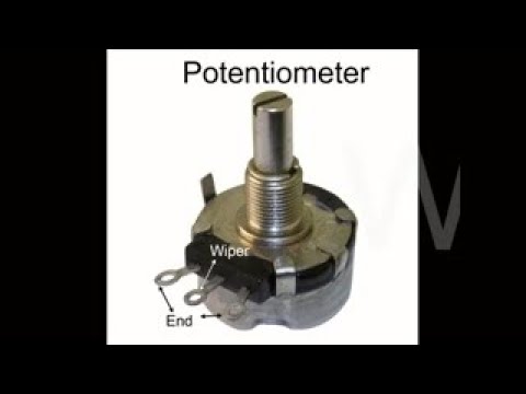
Image taken from the YouTube channel Sportsmith , from the video titled How to test a Potentiometer – Potentiometer testing tutorial. .
The potentiometer, often called a "pot," is a ubiquitous component in the world of electronics. It’s a simple yet ingenious device that acts as a variable resistor, allowing for precise control of voltage and current in a circuit. From volume controls on audio equipment to dimmers in lighting systems and position sensors in robotics, the potentiometer’s applications are incredibly diverse.
The Significance of Resistance Testing
At the heart of a potentiometer’s functionality is its resistance. Its resistance value dictates its ability to control the flow of electricity. Over time, or due to environmental factors, a potentiometer’s resistance can drift from its specified value. This deviation can lead to erratic behavior, reduced performance, or even complete failure of the circuit it serves.
Therefore, regularly testing a potentiometer’s resistance is crucial for maintaining the functionality and reliability of electronic devices. Identifying resistance issues early allows for timely repairs or replacements. This proactive approach prevents potentially costly and inconvenient system failures.
The Role of Quality Test Leads
Before diving into the testing procedure, it’s essential to acknowledge the importance of reliable test leads. The accuracy of any resistance measurement is only as good as the quality of the connection between the multimeter and the potentiometer.
Poor quality leads can introduce additional resistance into the circuit. This leads to inaccurate readings and potentially misdiagnosis of the potentiometer’s condition. Investing in high-quality test leads ensures a secure and accurate measurement. This is fundamental for reliable troubleshooting.
Article Objective: A Step-by-Step Guide
This article aims to provide a clear, step-by-step guide for accurately measuring the resistance of a potentiometer. We will cover everything from understanding the basic principles of resistance to interpreting the measurements obtained with a multimeter.
By following this guide, you’ll be equipped with the knowledge and skills necessary to confidently assess the health of your potentiometers. This knowledge allows you to ensure the continued performance of your electronic projects and equipment.
The article excerpt concluded with a look at the importance of quality test leads and a preview of our step-by-step guide. But before we get into the practicalities of testing, let’s solidify our understanding of what a potentiometer is and how it functions at a fundamental level. This knowledge is key to correctly interpreting the measurements you’ll be taking.
Understanding Potentiometers: Variable Resistance Explained
A potentiometer, in its essence, is a variable resistor. This simple definition unlocks its core function. Unlike a fixed resistor that offers a constant resistance value, a potentiometer allows you to adjust the resistance within a circuit.
This adjustability is what makes it so versatile in a wide array of electronic applications.
Resistance: The Foundation of Control
To fully grasp how a potentiometer works, we must first define resistance itself. In the context of electrical circuits, resistance is the opposition to the flow of electric current. Think of it as a bottleneck in a pipe, restricting the amount of water that can flow through. The higher the resistance, the less current can pass through a circuit for a given voltage.
Measuring Resistance: Ohms and the Greek Letter Omega (Ω)
Resistance is measured in Ohms, denoted by the Greek letter Omega (Ω). A higher Ohm value indicates a greater resistance to current flow. For example, a 100Ω resistor offers significantly less resistance than a 1000Ω (1kΩ) resistor. Multimeters are essential for measuring resistance in circuits. The multimeter setting in Ohms (Ω) should be used. The leads are connected to the component to reveal the resistance value.
Potentiometers in Action: Controlling the Flow
So, how does a potentiometer actually control resistance? Inside a potentiometer is a resistive element, typically a strip of carbon or a length of wire. A sliding contact, known as the wiper, moves along this element. This wiper is connected to a center terminal.
The resistance between the center terminal and either of the outer terminals varies depending on the wiper’s position. When the wiper is closer to one end, the resistance between that end and the center terminal is low, while the resistance to the other end is high.
By turning the potentiometer’s shaft, you effectively move the wiper, changing the resistance and, consequently, the current flowing through the circuit. This controlled variability is what allows potentiometers to act as volume controls, dimmers, and position sensors.
The multimeter setting in Ohms (Ω) should be used. The leads are connected to the potentiometer to measure resistance. It’s important to have a good understanding of this foundation before moving on.
Preparing for the Test: Tools and Materials Checklist
Before diving into the process of measuring a potentiometer’s resistance, gathering the right tools and ensuring their proper functionality is paramount. A well-prepared workspace minimizes errors and ensures accurate results.
Essential Tools and Materials
Let’s break down the essential components required for this task:
-
Working Potentiometer: This might seem obvious, but ensuring your potentiometer is in good condition is crucial. Visually inspect it for any physical damage. The shaft should turn smoothly without excessive play or binding.
-
Reliable Multimeter: A multimeter is the centerpiece of this test. It must be capable of accurately measuring resistance (Ohms). Both analog and digital multimeters can be used, but digital multimeters generally provide more precise readings. Ensure the multimeter’s battery is sufficiently charged for accurate readings.
-
Quality Test Leads: Often overlooked, test leads play a critical role in obtaining reliable measurements. Invest in test leads with secure connections and well-insulated wires. Frayed or poorly connected leads can introduce resistance into the circuit, leading to inaccurate results. Check the continuity of the leads themselves before beginning the test.
Deep Dive into Tool Selection
The Potentiometer: Assessing Condition
Before testing, verify the potentiometer’s stated resistance value, typically printed on the component itself. This allows you to compare your measured values against the expected range. If a potentiometer is visibly damaged or feels rough when turned, it may be unreliable for testing purposes.
Multimeter Considerations
While many multimeters can measure resistance, some offer features that can improve accuracy. Auto-ranging multimeters automatically select the appropriate resistance range, simplifying the measurement process. Higher-resolution multimeters can display more decimal places, providing greater precision.
The Unsung Hero: Test Leads
Test leads are more than just wires; they are the interface between the multimeter and the component being tested. High-quality leads are made with durable materials and offer secure connections. Look for leads with gold-plated connectors, as they resist corrosion and provide better conductivity. Regularly inspect the leads for any signs of wear and tear, and replace them as needed. Alligator clips are a great addition to quality test leads!
Optional Visual Aid
Consider including a photograph displaying all the necessary tools and materials. This can be beneficial for visual learners and helps to ensure that readers have all the required items before proceeding.
The careful selection of tools and materials lays the groundwork for successful potentiometer testing. Now, with our workspace prepped and components verified, it’s time to move into the core of our exploration: the step-by-step measurement process. This section will serve as your practical guide, walking you through each stage with clear instructions and essential considerations for achieving accurate results.
Step-by-Step Guide: Measuring Potentiometer Resistance
This section provides a detailed guide on accurately measuring a potentiometer’s resistance using a multimeter. Follow these steps carefully for optimal results.
Safety First
Before you begin, it’s critical to prioritize safety.
Always ensure the circuit containing the potentiometer is de-energized. This means disconnecting the power source.
Working on a live circuit can lead to electrical shock and damage to your equipment.
Double-check that the power is off before proceeding with any measurements.
Step 1: Multimeter Setup
The multimeter is your primary tool for measuring resistance. Proper setup is essential.
-
Turn on the Multimeter: Locate the power switch and turn the multimeter on. Allow it a few seconds to initialize.
-
Select the Ohms (Ω) Setting:
- Locate the dial or selector switch on your multimeter.
- Rotate the dial until it points to the Ohms (Ω) symbol. This symbol represents resistance.
- Select the appropriate range. If your multimeter has multiple Ohms ranges (e.g., 200 Ω, 2 kΩ, 20 kΩ), start with the highest range. If the reading is very small, reduce the range for a more precise measurement.
Step 2: Identifying Terminals
Potentiometers typically have three terminals. Correct identification is crucial for accurate measurements.
- Visually Inspect the Potentiometer: Look for markings or labels near each terminal.
- Refer to the Datasheet (If Available): The datasheet will provide a clear diagram of the terminal layout.
- Common Configuration: In many potentiometers, the center terminal is the wiper, while the two outer terminals connect to the ends of the resistive element.
Step 3: Measuring Total Resistance
This step determines the total resistance value of the potentiometer.
-
Connect the Test Leads:
- Plug the black test lead into the COM (common) jack on the multimeter.
- Plug the red test lead into the jack labeled VΩ or Ohms (Ω).
- Connect the test leads to the two outer terminals of the potentiometer. The order usually doesn’t matter for total resistance measurement.
-
Record the Resistance Value:
- Observe the reading displayed on the multimeter screen.
- This value represents the total resistance of the potentiometer, measured in Ohms (Ω).
- Record this value for later comparison.
Step 4: Measuring Wiper Resistance
The wiper’s resistance varies as you turn the potentiometer’s shaft. This step measures that variance.
-
Connect the Test Leads:
- Keep one test lead connected to one of the outer terminals.
- Connect the other test lead to the wiper terminal (usually the center terminal).
-
Record Initial Resistance:
- Note the resistance value displayed on the multimeter. This is the resistance between the wiper and that outer terminal.
-
Rotate and Observe:
- Slowly turn the potentiometer’s shaft.
- Observe how the resistance value on the multimeter changes as you turn the shaft. The resistance should either increase or decrease smoothly.
-
Repeat for the Other Terminal:
- Move the test lead from the first outer terminal to the other outer terminal.
- Repeat the process of turning the shaft and observing the change in resistance.
- The resistance change should be inverse to the first measurement.
Step 5: Interpreting the Results
Understanding the measurements is key to assessing the potentiometer’s condition.
-
Compare to Stated Value:
- Compare the measured total resistance to the value printed on the potentiometer’s body or in its datasheet.
- A significant deviation suggests a problem.
-
Tolerance Ranges:
- Potentiometers have a tolerance range (e.g., ±10%). This means the actual resistance can vary slightly from the stated value.
- Acceptable readings fall within this range.
-
Wiper Smoothness:
- The wiper resistance should change smoothly as you turn the shaft.
- Erratic jumps or dead spots indicate wear or damage.
-
Potentiometer Health:
- A total resistance reading significantly outside the tolerance range suggests a faulty potentiometer.
- Inconsistent wiper readings or a complete lack of resistance indicate internal damage or wear.
- These issues may necessitate potentiometer replacement.
The careful selection of tools and materials lays the groundwork for successful potentiometer testing. Now, with our workspace prepped and components verified, it’s time to move into the core of our exploration: the step-by-step measurement process. This section will serve as your practical guide, walking you through each stage with clear instructions and essential considerations for achieving accurate results.
Troubleshooting Resistance Issues: Identifying and Resolving Problems
Even with meticulous preparation and adherence to best practices, you might encounter unexpected issues during potentiometer resistance testing. Understanding common problems and their solutions is crucial for accurate diagnosis and effective repairs. This section outlines frequent resistance-related problems, their potential causes, and troubleshooting steps.
Inconsistent Resistance Readings
Fluctuating or unstable resistance values during measurement can be frustrating.
Instead of providing a stable reading, the multimeter display jumps around erratically. This issue often points to connection problems or internal potentiometer faults.
Potential Causes
- Loose Connections: The most common culprit is poor contact between the test leads and the potentiometer terminals. Oxidation or dirt on the terminals can impede electrical flow, causing erratic readings. Ensure the leads are firmly attached and clean.
- Faulty Test Leads: Damaged or worn-out test leads can introduce resistance or intermittent connections.
- Worn Wiper Contact: Inside the potentiometer, the wiper arm makes contact with the resistive element. Over time, this contact can wear down, leading to inconsistent readings as the wiper moves across the element.
- Internal Potentiometer Damage: Physical damage to the resistive element or internal connections within the potentiometer can also cause erratic behavior.
Solutions
- Clean Terminals and Test Leads: Use a contact cleaner to remove any oxidation or debris from the potentiometer terminals and test lead tips. Ensure a clean, secure connection.
- Check Test Lead Integrity: Inspect the test leads for any signs of damage, such as frayed wires or loose connectors. Replace the leads if necessary.
- Inspect the Potentiometer: Visually inspect the potentiometer for any signs of physical damage, such as cracks or loose components.
- Wiper Arm Lubrication: In some cases, applying a small amount of specialized potentiometer lubricant to the wiper arm can improve contact and reduce inconsistent readings. However, use the correct type of lubricant, as some may damage the potentiometer.
- Replace the Potentiometer: If the problem persists after addressing the above issues, the potentiometer may be internally damaged and require replacement.
Unexpectedly High or Low Resistance Readings
The multimeter displays a resistance value significantly different from the potentiometer’s specified value, it raises questions.
This could be much higher or lower than the expected range.
Potential Causes
- Incorrect Multimeter Range: If the multimeter is set to an inappropriate range, it may display inaccurate readings.
- Parallel Resistance: If the potentiometer is still connected in a circuit, other components in parallel with the potentiometer can affect the resistance measurement. The multimeter measures the combined resistance of all parallel paths.
- Potentiometer Degradation: Over time, the resistive element within the potentiometer can degrade, leading to changes in resistance value. Exposure to heat, humidity, or excessive current can accelerate this process.
- Component Failure: In some cases, the resistive element can fail partially, leading to an abnormally high or low resistance.
Solutions
- Verify Multimeter Range: Ensure the multimeter is set to the appropriate resistance range for the potentiometer being tested. Start with the highest range and reduce it until you get a stable reading.
- Isolate the Potentiometer: Disconnect the potentiometer from the circuit before measuring its resistance to eliminate the effects of parallel resistance.
- Consult Datasheet: Compare the measured resistance value to the potentiometer’s datasheet specifications. A significant deviation from the specified value indicates a problem.
- Consider Replacement: If the resistance value is significantly outside the specified tolerance, the potentiometer may be failing and should be replaced.
No Resistance Reading
The multimeter displays an open circuit (OL) or infinite resistance, indicating a complete break in the circuit.
Potential Causes
- Broken Circuit: A break in the resistive element or internal wiring within the potentiometer prevents current flow.
- Severely Corroded Terminals: Excessive corrosion on the terminals can prevent electrical contact.
- Faulty Multimeter or Test Leads: A malfunctioning multimeter or damaged test leads can also produce a false "no resistance" reading.
Solutions
- Check Continuity: Use the multimeter’s continuity testing function to check for breaks in the resistive element and internal wiring.
- Clean Terminals: Thoroughly clean the potentiometer terminals to remove any corrosion.
- Verify Multimeter Function: Test the multimeter and test leads by measuring the resistance of a known good resistor. If the multimeter still displays an open circuit, the meter or leads may be faulty.
- Replace the Potentiometer: If the potentiometer shows no continuity after cleaning and testing, it is likely damaged beyond repair and requires replacement.
The Influence of External Factors
External factors can play a subtle but important role in resistance measurements.
Voltage Effects
While potentiometers are primarily passive components, applying excessive voltage beyond their rating can cause damage. Testing resistance requires minimal voltage from the multimeter itself, but be aware of voltage limitations in circuit applications. Overvoltage can lead to component failure and inaccurate readings in the long run.
Temperature Effects
Temperature variations can affect the resistance of the potentiometer’s resistive element. Most potentiometers have a specified temperature coefficient that indicates how much the resistance will change per degree Celsius (or Fahrenheit). For high-precision applications, consider the ambient temperature and its potential impact on resistance measurements. High temperatures can increase resistance, while low temperatures can decrease it.
By understanding these potential issues and their solutions, you can effectively troubleshoot resistance problems in potentiometers and ensure accurate measurements for optimal performance.
Potentiometer Resistance Test: Frequently Asked Questions
These frequently asked questions provide further clarification on testing potentiometers.
What does the total resistance reading of a potentiometer tell me?
The total resistance reading between the two outer terminals indicates the potentiometer’s overall resistance value. This helps verify if it matches the potentiometer’s specified resistance rating, as a significant deviation may indicate damage. The appropriate test for resistance test on potentiometer would involve this step.
Why is it important to rotate the potentiometer knob during the resistance test?
Rotating the knob while measuring resistance between the center terminal (wiper) and one of the outer terminals allows you to check the full range of resistance adjustment. It ensures there are no dead spots or sudden jumps in resistance, indicating a smooth and consistent change in resistance as the knob is turned.
What does it mean if the resistance reading between the wiper and either outer terminal is zero?
A zero-ohm reading between the wiper and either outer terminal when the potentiometer is not at its extreme position usually means there is a short circuit within the potentiometer. This makes the device faulty. An appropriate test for resistance test on potentiometer would involve using Ohms Law.
Can I test a potentiometer while it’s still connected in a circuit?
Ideally, you should disconnect the potentiometer from the circuit before testing. Other components in the circuit can influence the resistance readings, leading to inaccurate results. Disconnecting it ensures you are only measuring the resistance of the potentiometer itself for a reliable assessment. It also helps to apply the appropriate test for resistance test on potentiometer.
So, you’ve tested your potentiometer – awesome! Knowing the apropritate est for resistance test on potentiometer is key to making sure everything’s working as it should. Now go forth and build something amazing!
